ATEN Technology ACS-1712 User Manual
Browse online or download User Manual for KVM switches ATEN Technology ACS-1712. ATEN Technology ACS-1712 User's Manual
- Page / 24
- Table of contents
- BOOKMARKS
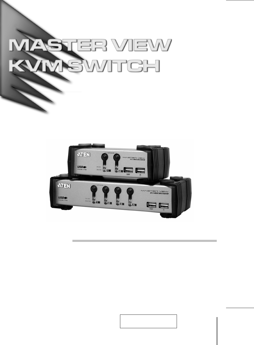
- ACS-1712 1
- ACS-1714 1
- Packing List 3
- Contents 4
- Overview 5
- Features 6
- Hardware Requirements 7
- Introduction 8
- Rear View* 9
- Installation 10
- Operation 11
- Port Selection 12
- Port ID Numbering 13
- Hotkey Summary Table 14
- OSD Operation 15
- OSD Navigation 16
- OSD Main Menu Headings 17
- The Function Keys 17
- 2001-07-05 18
- Factory Default Settings 20
- OSD Security 21
- Appendix 22
- Specifications 23
Summary of Contents
User ManualACS-1712ACS-17142001-07-05
InstallationBefore you Begin1. Make sure that power to all the devices you will be connectingup have been turned off. You must unplug the power cords
OperationHot PluggingThe Master View ACS-1712 / ACS-1714 supports USB hot plugging -components can be removed and added back into the installation by
Port SelectionThe Master View ACS-1712 / ACS-1714 provides three methods to obtaininstant access to any computer on your installation: Manual; Hotkey;
Port ID NumberingCPU ID NumberingEach CPU port on a Master View installation is assigned a single digit number(1 or 2 for the ACS-1712; 1 to 4 for the
Hotkey Summary TableCombination Action[Ctrl] + [Ctrl] Invokes OSD (Default)[Scroll Lock] + [Scroll Lock] Invokes OSD (Alternate Method)[Ctrl]+[Shift]+
OSD OperationOSD OverviewOn Screen Display (OSD), provides a menu driven interface to handle thecomputer switching procedure. Although Hotkey switchin
OSD NavigationM [Esc] cancels the current selection, or dismisses the current menu andmoves back to the menu one level above. If you are at the highes
OSD Main Menu HeadingsHeading ExplanationPN This column lists the Port ID numbers for all the CPU ports on theinstallation. The simplest method to acc
F5-F8 PREV USB / NEXT USBM Pressing [F5] Switches access to the USB peripherals from the currentlyactive computer to the Previous one on the installat
F10 SET UPPressing [F10] brings up the OSD configuration menu. To change a setting:1. Move the highlight bar through the list using the Up and Down Ar
NOTE: This equipment has been tested and found to comply withthe limits for a Class B digital device pursuant to Subpart J of Part15 of the FCC Rules.
Setting FunctionSET PASSWORD Allows you to set a password in order to control access tothe console. See OSD Security (p. 17) for passwordsetting deta
OSD SecurityIn order to prevent unauthorized access to the computers, the OSD provides apassword security feature. If a password has been set, the OSD
AppendixTroubleshootingSymptom Possible Cause ActionErraticbehavior.Unit not receivingenough power underself-poweredoperation.Use the Power Adapter th
SpecificationsFunction ACS-1712 ACS-1714 Computer Connections 2 4CPU Port Selection Front Panel Switches; Hotkeys; OSDUSB Port Selection Hotkeys; OSDL
Limited WarrantyIN NO EVENT SHALL THE DIRECT VENDOR’S LIABILITY EXCEED THEPRICE PAID FOR THE PRODUCT FROM THE DIRECT, INDIRECT, SPECIAL,INCIDENTAL OR
Packing ListThe complete Master View ACS-1712 / ACS-1714 package consists of:M One ACS-1712 or ACS-1714 KVM SwitchM One Power AdapterM One User Manual
ContentsOverview . . . . . . . . . . . . . . . . . . . . . . . . . . . . . . . . . . . . . . . . . . . . . . . . . . . . . . 1Features. . . . . . . .
OverviewThe Master View ACS-1712 and ACS-1714 represent a revolutionary newdirection in KVM (Keyboard, Video, Mouse) Switches. The ACS-1712 andACS-171
FeaturesM Dual Function KVM-USB SwitchM One Console Controls 2 (ACS-1712 ) or 4 (ACS-1714 ) Computers and TwoAdditional USB DevicesM USB Keyboard and
Hardware RequirementsConsoleM A VGA, SVGA, or Multisync monitor capable of the highest resolution thatyou will be using on any computer in the install
IntroductionFront View*1. Port Selection SwitchesM Press a switch to access the computer attached to the corresponding port.M Pressing Buttons 1 and 2
Rear View*1. Power JackThe power adapter cable plugs in here.2. Console Port SectionM The two type A USB connectors (upper row) are for USB peripheral
Related products and manuals for KVM switches ATEN Technology ACS-1712
 (20 pages)
 (80 pages) (167 pages)
© 2020, manymanuals.com. All rights reserved. | 1.452 s |
 Manymanuals.com
 Manymanuals.de
 Manymanuals.fr
 Manymanuals.it
 Manymanuals.pl
 Manymanuals.cz
 Manymanuals.es
 Manymanuals-pt.com
Comments to this Manuals